Posts

Non-linear Circuit Am Demodulation

Image
Ghost Talk: Mitigating EMI Signal Injection Attacks against Analog Sensors by Denis Foo Kune demonstrates the use of microphone as an AM receiver. I was curious how it was possible for circuits to unintentionally receive AM signals and demodulate it. The antenna theory that long wires which can resonate with the carrier frequency of RF wave was intuitive, but the circuits retrieving the envelope signal was mysterious to me. Through experiments, I found that when high frequency signals enter non-linear circuits such as diodes, PN transistors, op amps, and many amplifier circuits, the output will create harmonics of the input frequency. For instance, let’s look at an amplifier circuit below. This circuit has a gain of 10 and is biased at 2.5V virtual ground. Op amps usually operates linearly, but when the output signal reaches toward the supply voltage, the output will start to clip and show op amp’s non-linear property. To exaggerate the non-linear property, this circuit is desi

Roborace Showcase at MCity

Image
On last Friday, which was May 21st, Roborace visited Mcity in the University of Michigan to show case its autonomous race car, Robocar. Robocar's first impression was astounding. Previous self-driving cars involved regular cars with regular seats. However, this race car was designed so that there is no seat. It looked like Formula 1 race cars with a higher cool factor. To achieve the autonomy, the race car uses a combination of Lidars, Radars, Sonars, and computer vision cameras. Unlike traditional self driving cars which has a roof mounted Lidar, Robo race has a couple of Lidar in the front wheel wells. I wonder the benefits of the side mounted Lidars over top mounted Lidars. I predict that due to its low height, top-mounted Lidar might cause a line of sight issue. As a consequence of side mounted Lidar in the front, the car introduces a blind spot due to large back wheel wells. Therefore, the back wheel is mounted with Sonars to compensate. In the top of the car seats the c

Let’s Build 5V Solar Charger Part 2

Image
Let’s Build 5V Solar Charger Part 2 Last week, I assembled step-up boost converter kit and put 6V solar panel to power up the chip. I did a final assembly inside a metal casing and taped the solar panel around the case to make the kit tidy as shown in the photo below. This week, I measured the output of the solar charger. I measured the open circuit voltage and short circuit current to calculate the power output. The voltage was measured at around 6V and current was measured at around 0.03Amp. This translates to around 200mW of energy. This is 1/5 of what the solar panel was advertised at. The product page advertised at 1W of output. I expected that the tiny circuit wouldn’t able to charge a power hungry smartphone. However, this might be sufficient enough to charge a small LED light for my bike. Considering that normal USB port’s maximum current output is 500mW, the solar panel’s output is decent.  For curiosity, I calculated how much energy I could save using

Let’s Build 5V Solar Charger

Image
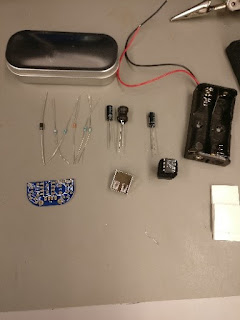
I am taking an online summer class at University of Minnesota regarding renewable energy. I took a project of building a solar charger to charge my bike LED light. This will be a fun small project. The items used for this project are Adafruit phone charger kit and 6V 1W solar panel.               The above kit is a basic step-up converter circuit PCB that converts a variable input voltage to 5V output. It is meant to use two 1.5V battery cells. However, for this project, I will use a solar panel instead. The solar panel is advertised to output 6V. According to the LTC1302 datasheet of the boost converter used in this kit, the input voltage has a range from 2V to 8V. Therefore, this solar panel rated for 6V output should be appropriate for this build. I soldered all the parts according to the instruction here: https://learn.adafruit.com/minty-boost/solder-it . This is an easy task to people who have prior experience with soldering. Next week, I will demo

Current Sensing 101

Image
Current Sensing 101 Now that starter project is done, it is time for real research. For the past week, I have been thinking of using current sense resistors for my research project. This blog post will introduce concepts of current sense resistors and how to use them. Measuring current using current sense resistor, op amp, ADC, and MCU The standard method of measuring current is to measure voltage drop over a resistor. The topology is shown in the above schematics. Ohm’s law can be applied to convert voltage measurement to current value using I = V/R. Current sense resistors are high precision low ohm resistors ranging from microohm to milliohms. Consider a 12V power source with a variable load resistance from 250 Ω to 1000 Ω . This converts to a current draw range of 12mA to 48mA. The voltage drop over a 0.01 Ω current sense resistor then ranges from 12uV to 48 uV. These are very small numbers and need to be amplified to the microcontroller voltage range of 0V

ESCAR 2017

Image
This week, I attended ESCAR Embedded Security in Cars conference in Ypsilanti, Michigan. As my first conference I attended, I learned the valuable lessons: insight to fields and areas I have not been introduced before and potential to network with people in industry and academia. One very interesting presentation was use of ChipWhisperer to perform side-channel attacks to crack passwords and encryption using differential power analysis on common processors such as STM32F2. During breaks, I attended multiple vendor booths and one in particular caught my attention. It was GRIMM. GRIMM engineers were able to have almost full access to one of the Ford Focus’s CAN bus without proprietary information. One thing that stood was how easy it is to get an access to the bus. In fact, they had a couple of demos where we could learn how to read packets to narrow down a function.  They gathered all the items from a single car from a junkyard. It is almost scary to know how easy it is to crack a

Single Sided Rowhammer Attack Part 2

In the last blog, I posted about the probabilistic nature of the single sided Rowhammer attack due to its random address selection. This week, I found that allocating more heap increases the frequency of bit flips. From my experiment, allocating 14GB memory instead of 1GB increased the chance of successful bit flips by more than 20 times. Google’s single sided row hammer test source code initializes 1GB of memory. My prediction is that the OS randomizes the virtual memory mapping to multiple areas of physical memory address. Therefore, when relatively small amount of memory is allocated, for example 1GB out of 16 GB, the memory will likely spread over multiple banks. Therefore, when a pair of addresses are accessed and flushed, they won’t meet the requirement that the addresses are in the same bank and different row. Furthermore, when the row hammer attack does successfully flip a bit, it can be outside the allocated space. In this case, we won’t able to check the result, unless